Quantcast
Channel: ArduinoDev.com
Viewing all 77 articles
Browse latest View live

Freematics OBD-II Adapter V2 sample completed

$
0
0

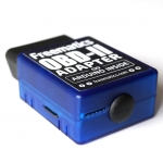
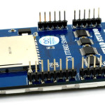
After our first Kickstarter campaign was over, we have been keeping up pushing the project Freematics forward, though the goal of the campaign wasn’t reached. The sample of Freematics OBD-II Adapter V2 is now under testing. The V2 has several changes and improvements. The most important one is the GPS support. One serial UART of STM32 was led out to 4 pins for connecting GPS module. The STM32 processor will process the NMEA data input from the connected GPS module and parse it. We have extended ELM327 AT command-set to provide access to the parsed data. The added commands are:

  • ATBR1 – setting serial baudrate for AT command line interface (default 38400bps)
  • ATBR2 – setting GPS serial baudrate (first setting turns on GPS parsing)
  • ATGPS – retrieving parsed GPS data
  • ATSGC – sending command to GPS module

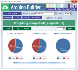
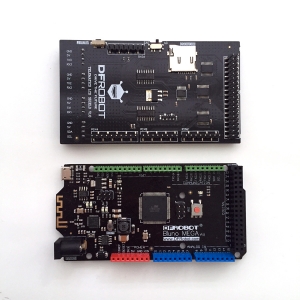
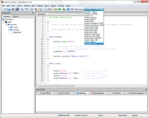
The second change is that the main controller has been replaced by ATMega328P. This change was made in consideration of several factors. ATMega644PA is large in size and has too much more hardware resources than is normally needed in most applications. ATMega328P has much smaller footprint so we can have more space on the board for other stuff. It also has lower power consumption. Switching to ATMega328P brings an additional advantage of the compatibility with standard Arduino UNO, so no Arduino IDE addon package is needed any more.

freematics_obd_v2_pcb

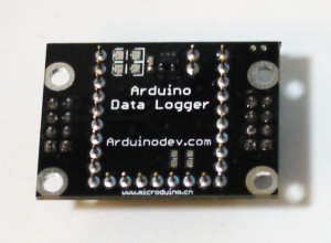
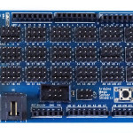
The PCB layout of Freematics OBD-II Adapter V2

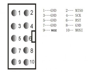
Please note that order of ICSP/SPI pins have been changed. Please be aware when connecting to USBasp programmer.

usbasp_10pin
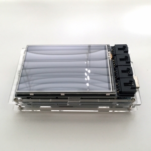
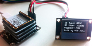
Another noticeable change is that we will open up two slots on the enclosure so that ICSP/SPI pins can be connected and microSD card can be plugged in and out without opening the enclosure.

freematics_obd_v2_2 freematics_obd_v2


Programming Guide for Freematics OBD-II Adapter V2 (Arduino compatible)

$
0
0

Freematics OBD-II Adapter V2 is a programmable device with OBD-II and GPS accessibility. Inside it is an ATMega328P (compatible with Arduino UNO) and a bunch of peripherals including accelerometer, gyro, temperature sensor, microSD socket and Bluetooth (BLE or BT 2.1) module. The adapter can optionally lead out a cable for SPI and I2C communication, or analog sensor input/output.

freematics_obd_1 freematics_obd_2

Hardware Programming Interface

The onboard ATMega328P is programmed via ICSP, either by USBasp or Arduino as ISP. Both ways are supported by Arduino IDE.

The 6-pin interface on the top-left is the SPI pins which is also the ICSP port for Arduino.

Freematics OBD-II adapter breakout pins

Freematics OBD-II Adapter V2 Pinouts

SPI pins as ICSP

Programming with USBasp

A USBasp programmer has 6 useful pins. To program with USBasp , connect the adapter’s SPI pins with USBasp’s pins as following:

usbasp_10pinAdapter SPI         USBasp

 MISO                        2-MISO
SCK                           4-SCK
RESET                      6-RST
GND                         8-GND
VCC 5V                    9-VCC (*)
MOSI                       10-MOSI


* Please be cautious that as some cheap USBasp programmers do not have good impulse filtering, it is recommended that the adapter is powered from the OBD-II port (12V input) instead of USBasp’s VCC pin in order to prevent possible damage to the board by impulse current on the moment of plugging the USBasp to computer.

Wiring with USBaspProgramming with Arduino as ISP

An common Arduino board can work as ISP for another Arduino board with Arduin ISP sketch loaded. To program with Arduino, connect the adapter’s SPI pins to Arduino’s ICSP pins and the reset pin to Arduino’s D10.

freematics_obd_wiring_2

Software Development Environment

Arduino IDE is the recommended development environment for Freematics OBD-II Adapter. Set board to Arduino UNO and everything is same as if programming an Arduino UNO.

arduino_ide_freematics

You can then use Arduino IDE to develop program for the Freematics OBD-II adapter. Following libraries can be used for access the onboard resources of the adaper:


Firmware

A basic firmware for the adapter is developed in form of an Arduino sketch. When loaded with the firmware (factory default),  the adapter works with our Freematics OBD iOS App out-of-box. Users can modify the firmware source code and involve their own one or interact with their own App.

The source code of firmware is on GitHub.


Links

Tomorrow we are part of the show

$
0
0

Tomorrow we will be part of the world’s biggest event for makers, the Maker Faire Bay Area! Last year in NYC, we came to the stage of Maker Faire for the first time and was deeply impressed and motivated by the event. In the following 8 months, we have done a lot towards the goal of our project. We went onto Kickstarter and got hundreds of backers after the campaign. We set up our online store for accepting orders from worldwide.We kept improving our key product, Freematics OBD-II Adapter and released V2 of it. Being in the maker movement, we are just motivated to go towards our goal while also being able to enjoy the the whole process.

We are so excited to come back to Maker Faire to show the world what we have done through the months. In this show, we will be presenting 3 major works.

Freematics OBD-II Adapter V2

This is the core product of the project. The V2 comes which has following changes/improvements:Freematics OBD-II Adapter

  • Faster OBD-II data access (up to 100Hz)
  • Built-in GPS support (10Hz data update rate)
  • ATMega328p as main controller (compatible with Arduino UNO)
  • SPI breakout slot for communication or programming via ICSP
  • MicroSD socket breakout slot for easy inserting/removing card

Freematics OBD-II Emulator V2

Our OBD-II emulator is really a derivative product which was originally made for our internal use only. When we tried pushing it to market, it got unexpected popularity so that we decided to make it better. The original version uses 9 knobs for adjusting the value of 9 OBD-II PIDs. The physical knobs are handy to use but in some cases when we want to adjust more PIDs or do it programmatically, a data interface is necessary. The V2 comes with a serial data interface of a simple AT command-set which goes through TTL, USB or Bluetooth. By sending AT command, the value of OBD-II PIDs can be altered and the change is reflected on the simulated data bus and finally on the OBD-II port. The physical knobs are removed as we will make a good PC software and iPad/iPhone App for the same and even better experience. As the emulator also provides TTL serial UART breakout, it is possible to control the emulator with an Arduino or other hardware. This can be used to emulate a standard OBD-II port on a vehicle which does not have one with actual data obtained by other means.

Arduino OBD-II Logger Kit based on Arduino DUE

We have been providing different Arduino OBD-II Logger Kits which are popular among makers who want to make a vehicle data logger with a display. The Kit #3 originally consist of an Arduino MEGA 2560 and a 2.8″ TFT LCD shield. It is to be upgraded to Arduino DUE and 3.2″ TFT LCD shield.

The above 3 highlights are what we will present at this Maker Faire. Come to see us if you are hanging around!

Arduino OBD-II Data Logger Kit Upgraded

$
0
0

The popular Freematics OBD-II data logger kit #3 has just got better. After coming back from the Maker Faire Bay Area, we upgraded the kit by replacing the 2.8″ TFT LCD screen shield with a newly designed 3.2″ TFT LCD shield with built-on I/O sockets and optional Bluetooth module. The new TFT LCD based on SSD1289 is perfectly supported by the latest revised version of MultiLCD library now. This makes screen larger (also faster) and eliminates the need for a I/O shield in the middle of TFT LCD shield and Arduino MEGA board. The Bluetooth (BLE or BT 2.1) capability is provided by a CC2540 module soldered on the back of the shield which is connected to Arduino MEGA’s Serial3.

Click here to learn more about the new kit #3.

Arduino Uploader 0.6 released with both GUI and CLI versions

$
0
0

Arduino Uploader now comes with GUI version which makes compiling and uploading an Arduino sketch to the board never easier. With no more than 3 clicks, you sketch will be running on your board. Take a look at the the screenshot. The command line version is also updated and have the same functionality as the GUI version while the former can be integrated into 3rd party applications (a real example: Mind+).

arduino_uploader_console arduino_uploader_report

Download Arduino Uploader

A tutorial for Arduino Builder

$
0
0

Arduino Builder is a tool for viewing and compiling Arduino sketch (source code) and programming the Arduino board with the compiled code (HEX code).

From this link you can pick the latest version and download. Once downloaded, extract the 7z compressed package to a new folder and you can launch Arduino Builder by running ArduinoBuilder.exe in the folder.

Before launching, please plug your Arduino to computer with USB cable, as the program will search for available serial ports appeared on your system and display them.

It’s only 3 steps for compiling your Arduino sketch and programming the Arduino with the compiled code

STEP 1: Set board type and operating frequency if necessary

Arduino Builder - Step 1


STEP 2: Load your sketch or HEX file

Click the “Load Sketch / Hex” button to choose a file to load and the content of the file will be displayed.

ab2


STEP 3: Choose serial port or programmer

Click one of the serial port or programmer button shown the whole procedure will begin. If you only want to compile the code into HEX file, click Build Only button.

Once started, the program will swith to console view in which the process of compiling and programming will be displayed as well as error message if there is any.

ab3

When the process completes with no error, a report with 3 pie charts will be shown from which you can grab a overview of the memory consumption for your Arduino’s FLASH, SRAM and EEPROM space.

ab4

At this point, everything is done. If you want to open a serial terminal and see some results from the board, choose a baudrate and click “Open” button or a serial port button. The content from serial port will be displayed in the console window.


// ]]>

Building an OBD-II + GPS data logger with Microduino

$
0
0

P1050336Right now an enhanced version for the Arduino OBD-II data logger kit is under development. The new kit will feature 10Hz GPS logging via MTK3329, OBD-II data logging via Arduino OBD-II adapter, and 3-axis accelerometer sensor data logging via MPU6050 embedded inside the adapter. What is more interesting is that the new kit will base on a variant of Arduino, named Microduino, with smaller size and better capability, stackable like normal Arduino, making the whole kit small and tidy.

For those who have previously ordered the Arduino OBD-II data logger kit, there is no worry about your investment, as the most worthy parts in the kit (OBD-II adapter and I2C OLED module) are still usable in the new kit, and there will also be an upgrade pack (including the new Microduino parts and MTK3329 GPS receiver) by the time the new kit is ready for order.

About Microduino

Let me briefly introduce about the Arduino variant. The Microduino features two types. The type Core, which is 100% compatible with Arduino UNO (ATMega328 based) in both software and hardware pinouts. The type Core+ is based on ATMega644P. They share the same board size and stackable shields. The Core+ is used for the new kit, which features:

  • 2 hardware serial UART (one for OBD-II adapter and one for GPS)
  • 64KB program memory / 4KB SRAM /2KB EEPROM
  • Stackable MicroSD/TF shield
  • Stackable FT232 USB shield (for uploading program)

A dedicated extension board is developed for the new kit. 2 serial UART pinouts and 2 I2C pinouts are available on the board for easy connection of Arduino OBD-II adapter and GPS receiver.

logger_board
The extension board for the new OBD-II data logger kit

For development environment, the standard Arduino IDE can be used with some mods. A better choice is to use CodeBlocks Arduino IDE which will provide you an out-of-box experience with this Arduino variant. You can also use Arduino Builder to compile and upload you pre-written sketch to the board.

 cb20130317
CodeBlocks Arduino IDE with Microduino support

Arduino Builder - Step 1Arduino Builder with Microduino support

P1050333
Running OBD-II OLED dashboard example

IMG_1791
Running OBD-II data logger sketch

Real-Time Arduino GPS Tracker w/ iPhone app

$
0
0

Just bumped into a website introducing a home-brew Arduino GPS tracker made up with a GPS and GSM shield.


OBD-II + GPS + G-force data logger based on Arduino MEGA2560

$
0
0

This will be the most comprehensive OBD-II data logger kit and also the biggest in size as it is based on Arduino MEGA2560. Te kit consists of:

With this kit, following data can be displayed and recorded to SD card.

  • OBD-II data (all PIDs available in vehicle)
  • GPS data (5Hz/10Hz update rate)
  • 3-axis accelerometer data
  • 3-axis gyro data
  • temperature sensor data

Gallery

Arduino MEGA I/O expansion shield LCD TFT shield for Arduino (back)

Wiring

With the MEGA I/O shield, it is very handy to connect everything. The connector from the OBD-II adapter should be plugged into the I2C socket on the I/O shield. The 4-pin connector from GPS receiver should be plugged into I/O shield’s UART2 socket.

mega_io_shield

OBD-II adapter line definition:

  • Red: VCC (5V)
  • Black: GND
  • Blue: SDA (or D20)
  • Yellow: SCL (or D21)

GPS line definition:

  • Red: VCC
  • Black: GND
  • Green: Tx (to Arduino Serial2 Rx or D17)
  • White: Rx (to Arduino Serial2 Tx or D16)


MEGA Logger

The MEGA Logger is a complete sketch developed for the kit working as a OBD-II and GPS data logger with live data display. The source code is available here. For getting started easier, a complete package containing the sketch and all referenced libraries is available here.

After being able to record all the data, it is then possible create a KML with Data2KML utility and display the data with Google Earth like this:

Wollongong Mount Dash

FAQ

Q: How to make the SD card socket on the TFT LCD shield work with Arduino MEGA 2560?

A: Go to <Arduino Dir>/libraries/SD/utility, open Sd2Card.h file, find and uncomment following line:

#define MEGA_SOFT_SPI 1

Open config.h file in sketch directory, uncomment this line:

#define SD_CS_PIN 10

And comment out this line:

#define SD_CS_PIN SS


Links

Arduino SD card picture viewer with TFT LCD shield

$
0
0

IMG_2687

I just started to play with TFT LCD screen with Arduino. I used Itead 2.8″ TFT shield which is said to work great with UTFT library. Taking into account that Arduino has too limited Flash to hold a full frame of picture, and that the shield has a SD card socket on the back, I decided to make a SD card picture viewer as my first approach.

The 8-bit AVR-based Arduino has not only limited storage but also limited computation power. It is impossible to decode JPEG or PNG on-the-fly with Arduino, nor is it possible to load a whole bitmap from SD card into SRAM. The image files have to be stored in raw data format and loaded and rendered portion by portion. The native data format of the TFT control chip is RGB565 (2 bytes for a pixel, 5 bits for red, 6 bits for green, 5 bis for blue). So I used MediaCoder, which is a universal media transcoder I developed, to generate the raw image data of RGB565. It can also convert video files to a sequence of image files.

You can get MediaCoder here for free. After the software is launched, click Add button to add your image or video files, or simply drag them into to the program window. To make MediaCoder generate image files, change the “Format” to “Image” on Video tab. By default, JPEG is the output format and this can be changed to “Raw” on the right side.


There is one more option to change and it is important. As our TFT shield likes to eat 16-bit RGB565 data, we need to change the colorspace to RGB565.

Finally, set an output folder and click the Start button to kick the conversion off. When converting video file, a sequence of image files will be generated in a specified interval and you can adjust the interval or specify the number of images you want to get for each video file.

After conversion is accomplished, you will get a bunch of .RAW files in the output folder. Now plug in the SD card to your computer, create a PICTURE folder on it and copy the generated files to the folder.

sd_picture_files


Now comes the Arduino part, all we need to do is uploading the sketch I wrote to Arduino, mounting the shield, inserting the SD card. Sit back and watch your pictures showing one by one on Arduino.

IMG_2677

IMG_2686

Cheers on the all new Arduino Yún!

$
0
0

Finally Arduino combies with Linux. The name is also brilliant! Yún(云) means cloud in Chinese language and that indiciates this Arduino goes up to the cloud, with either WIFI or RJ45. There is USB host and MicroSD socket onboard too.
Arduino Yún
Arduino_YunCheck out more details on Arduino Blog.


Switching among Arduino LCD shields or modules with ease

$
0
0

arduino_lcd_shieldsRecently I developed a library for ease the job of displaying texts and numbers on different LCD/OLED modules. This is mainly for my OBD-II data logger project which can be made up of different sets of Arduino hardware. I named the library as Arduino Text Display Library for Multiple LCD, or short as MultiLCD.

The library encapsulates several libraries for various Arduino LCD/LED display shields or modules into a set of unified APIs.

Currently it supports these hardware:

  • DFRobot LCD4884 shield
  • Nokia 3310/5100 LCD module
  • LCD1602 shield
  • SSD1306 OLED module
  • ZT I2C OLED module

The library includes fonts data for ASCII characters (5×7) and digits (8×8, 16×16). By using the library, it is extremely simple for display texts and numbers on desired position on a LCD screen, while very little change is needed to switch from one LCD module to another.

multilcd

To use a specific shield or module as the display for Arduino, you need to include library header at the beginning of the sketch.

#include <MultiLCD.h>

And use one of following declarations before your code.

For SSD1306 OLED module:

LCD_SSD1306 lcd;

For LCD4884 shield or Nokia 5100 module:

LCD_PCD8544 lcd;

For LCD1602 shield:

LCD_1602 lcd;

For ZT I2C OLED module:

LCD_ZTOLED lcd;

A demo Arduino sketch is like followng.

#include <Wire.h>
#include <MultiLCD.h>

LCD_SSD1306 lcd; /* for SSD1306 OLED module */

void setup()
{
    lcd.begin();
    lcd.clear();

    lcd.setCursor(0, 0);
    lcd.print("Hello, world!");

    lcd.setCursor(0, 1);
    lcd.printLong(1234567890, FONT_SIZE_SMALL);

    lcd.setCursor(0, 2);
    lcd.printLong(1234567890, FONT_SIZE_MEDIUM);

    lcd.setCursor(0, 3);
    lcd.printLong(12345678, FONT_SIZE_LARGE);
}

void loop()
{
}


Update 5/30: added bitmap drawing (SSD1306 only)

oled_smile

Update 5/29: 2.8″ TFT shield supported

Arduino_TFT_Texts

Links:

Arduino Builder updated and synced with Arduino IDE 1.6.4

$
0
0

Arduino Builder was just updated. The new release contains header and library files from Arduino IDE 1.6.4. AVR toolchain and AVRDUDE are also updated to latest version.

Download the latest release from here.

Arduino library for SIM800 for GPRS/HTTP communication

$
0
0

Recently I obtained a cheap (under $8) teeny-tiny SIM800 breakout board. The serial UART interfaced SIM800 makes it very easy for any embedded system to add cellular network access and connect to the cloud. The breakout board has a Mirco SIM seat the the back of the PCB.

 11054406_10206512499749880_7107441772337360198_n 11267482_10206512499909884_3327504921710956026_n

After some efforts, I managed to make it work with an Arduino Leonardo. Basically 5 wires are needed to connect the module to Arduino and they connect pins of VCC/GND/Rx/Tx/Reset. This is quite straight-forward. The module’s VCC can’t directly connected to that of Arduino as SIM800 requires a working voltage of 3.7V-4.2V. So a dixode is needed to step down the voltage a bit. The basic programming to make the module work was soon done by referring to the SIM800 AT command-set manual.

11264020_10206518105610023_3666326037796657461_nMy target is continuously sending HTTP requests containing sensor data to a web server (data as URL argument) and retrieve the response containing command. To make it easier for myself and other people who use the same SIM800 based modules, I started to write an Arduino library for this purpose. It contains only what I need at the moment. That includes what is needed to perform HTTP request and retrieving GSM location data. I am expanding it graudually. The library is hosted on GitHub and an exmple sketch is also available. The sketch can be as simple as following.

#include "SIM800.h"

#define APN "connect"
#define con Serial
static const char* url = "http://arduinodev.com/datetime.php";

CGPRS_SIM800 gprs;

void setup()
{
  con.begin(9600);
  while (!con);

  for (;;) {
    con.print("Resetting...");
    while (!gprs.init());
    con.println("OK");
    
    con.print("Setting up network...");
    byte ret = gprs.setup(APN);
    if (ret == 0)
      break;
    con.print("Error code:");
    con.println(ret);
  }
  con.println("OK");

  for (;;) {
    if (gprs.httpInit()) break;
    con.println(gprs.buffer);
    gprs.httpUninit();
    delay(1000);
  }
}

void loop()
{
  gprs.httpConnect(url);
  while (gprs.httpIsConnected() == 0) {
    // can do something here while waiting
  }
  if (gprs.httpState == HTTP_ERROR) {
    con.println("Connect error");
    return; 
  }
  con.println();
  gprs.httpRead();
  int ret;
  while ((ret = gprs.httpIsRead()) == 0) {
    // can do something here while waiting
  }
  if (gprs.httpState == HTTP_ERROR) {
    con.println("Read error");
    return; 
  }

  // now we have received payload
  con.print("[Payload]");
  con.println(gprs.buffer);

  // show position
  GSM_LOCATION loc;
  if (gprs.getLocation(&loc)) {
    con.print("LAT:");
    con.print(loc.lat, 6);
    con.print(" LON:");
    con.print(loc.lon, 6);
    con.print(" TIME:");
    con.print(loc.hour);
    con.print(':');
    con.print(loc.minute);
    con.print(':');
    con.println(loc.second);
  }
}

Arduino Builder 0.9.1 Released

$
0
0

The new version has added an option of “Optimize for Speed” which Arduino IDE does not provide. This will make your sketch compiled into faster code but larger in size. Download the latest release from here.

ArduinoBuilder-3


Simple test sketch for UTouch library

$
0
0

Here is a simplest touch screen test sketch (display X,Y on serial) using UTouch library for common Arduino LCD shield.

#include <UTouch.h>

UTouch  myTouch( 6, 5, 4, 3, 2);

void setup()
{
  myTouch.InitTouch();
  myTouch.setPrecision(PREC_MEDIUM);
  Serial.begin(115200);
}

void loop()
{
  while (myTouch.dataAvailable())
  {
    myTouch.read();
    long x = myTouch.getX();
    long y = myTouch.getY();
    if (x != -1 && y!=-1 && x != 319)
    {
      Serial.print("X=");
      Serial.print(x);
      Serial.print(" Y=");
      Serial.println(y);
    }
  }
  delay(20);
}

Tested with XPT2046 / ADS7843 touchscreen driver on Arduino MEGA.

kit3-lcd35-2 kit3-lcd35-1
Newly released Telematics Shield with 3.5″ LCD (R61581 controller)

Arduino Builder updated

$
0
0

Arduino Builder was recently updated. In this release, AVR GCC has been upgraded to version 4.9.1. Arduino core and libraries files have been synchronised with Arduino IDE 1.7.10. Some minor UI issues were solved. If you don’t know about the software, head for its home page.

Viewing all 77 articles
Browse latest View live