After working out and merchandising the Arduino OBD-II adapter, I was thinking of putting up some kits based on the adapter with which people can start playing Arduino with cars more easily. A useful application as my initial approach is a OBD-II data logger device which reads out sensor data from vehicle and records the data on mass storage (e.g. SD card). Besides data logging, it better also displays some realtime data and states on a screen. The logged data also needs something to illustrate, possibly into a chart. All these thoughts brought up the Arduino OBD-II data logger kit and this website.
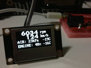
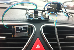
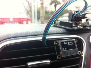
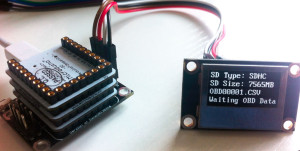
The logger displays (on a 128×64 OLED display module) and records (to a SD card) selected OBD-II data (engine RPM, speed etc.). The bright monochrome OLED display has very good visibility in daylight regardless of its small size. You can place it anyway on your dashboard that you feel comfortable. By pulling out the SD and inserting into computer (with a SD reader or a built-in one), the data can be easily illustrated into a chart.
Objectives:
- Displaying realtime engine RPM and vehicle speed on OLED screen
- Recording realtime OBD-II data to SD card in text-based CSV file format
- Illustrating the recorded data in as chart
Recorded data includes:
- Engine RPM
- Speed
- Throttle position
- Engine load
- Engine coolant temperature
- Intake manifold absolute pressure
- Intake temperature
Of course any data that can be obtained from OBD-II can be recorded. The recorded data is stored in a SD card in the format of CSV. Each line represents a record with time, data type and data value like this:
[Time Elapsed],[Data Type],[Data Value]
Time Elapsed is the time elapsed in milliseconds since previous data record. Data type is the OBD-II pid number which is defined in the OBD-II library (e.g. 0xC is engine RPM). Here is an example data clip:
169,D,0
171,11,12
170,43,21
165,B,30
175,C,705
169,D,0
170,11,12
171,43,21
170,C,702
169,D,0
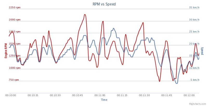
You can write you own software to analyze and illustrate the recorded data. If you don’t want to do any programming on this, an online service is set up for illustrating the data recorded in a graphic chart like this:
![OBD Data Chart]()
To view your own chart, simply plug the SD card into your computer (either with built-in or external SD card reader), choose the CSV file, and click the view button. If you don’t have a recorded file, you can still click the Demo link to view some sample data.
Pictures
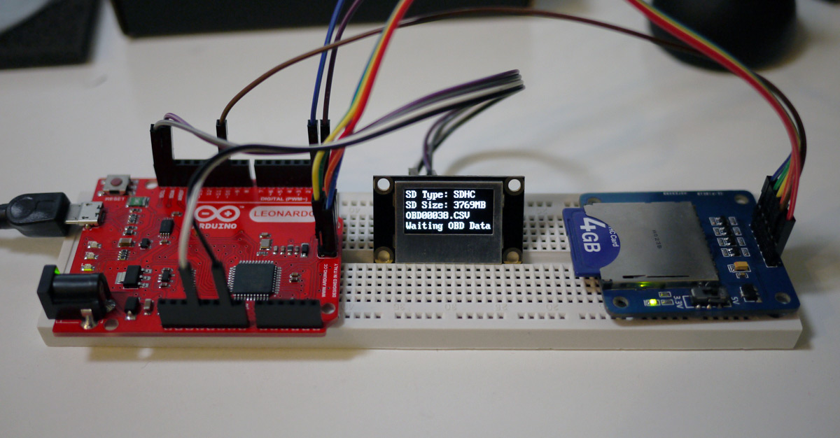
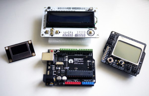
![Arduino Leonardo Data Logger]()
Kit with Arduino Leonardo
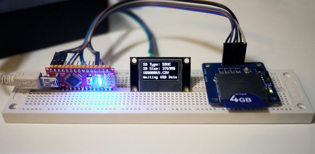
![obdkit_nano]()
Kit with Arduino Nano
![oled1]()
![oled2]() Kit in car
Kit in car
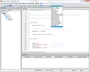
Source Code
The source code of this OBD-II data logger uses following Arduino libraries:
- SD Library (for accessing SD card)
- Wire Library (for communicating with I2C OLED display module)
- MultiLCD (a custom library encapsulating OLED & PCD8544 access routines)
- Arduino OBD-II Library (for accessing OBD-II adapter)
Wiring Up
Connecting Arduino with SD breakout
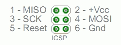
The SD breakout board is connected with Arduino via SPI. On Arduino Leonardo, the SPI pins are at the ICSP connector (see this for difference in SPI spins on different Arduino boards).
![]()
The SD breakout board has following 6 pins to be wired:
- VCC -> Arduino ICSP 2 (VCC)
- GND -> Arduino ICSP 6 (GND)
- DO -> Arduino ICSP 1 (MISO/D12)
- DI -> Aruino ICSP 4 (MOSI/D11)
- CLK -> Arduino ICSP 3 (SCK/D13)
- CS -> Arduino D10
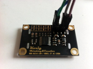
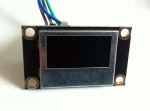
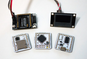
Connecting Arduino with I2C OLED module
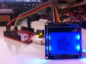
The OLED module can be powered by either 3.3V or 5V. It has 8 pins at the back and 4 of them need to be wired.
![oled4]()
![oled3]()
Pins to to wire:
- 3v3 -> Arduino 3.3V
- GND -> Arduino GND
- SDA -> Arduino SDA (A4)
- SCL -> Arduino SCL (A5)
Connecting Arduino with OBD-II
The OBD-II adapter provides power for Arduino and the connected devices and serial UART connection with Arduino.
- TxD (white line) – Arduino UART RxD (D0)
- RxD (green line) – Arduino UART TxD (D1)
- 5V (read line) – Arduino 5V
- GND (black line) – Arduino GND
Kit for Order
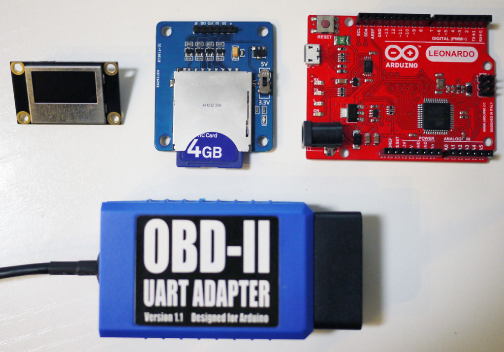
If you like this open-source Arduino OBD-II logger kit, you can order it now. The kit consists of:
- Arduino OBD-II adapter (x1)
- Arduino Leonardo / Arduino Nano (x1)
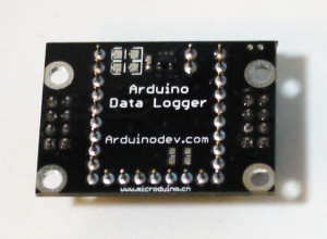
- SD breakout board (SDHC compatible, SD card not included) (x1)
- I2C OLED display module (128×64 pixels) (x1)
- Wires needed for connecting all parts (x10)
- Complete source code (sketch & libraries)
![obdkit1]()
The complete source code will be provided so you can freely modify it to change or add features you need (e.g. changing the display or logging other data you need).
To order this kit, please click HERE.
zp8497586rq