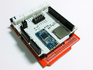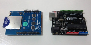
I just started to play with TFT LCD screen with Arduino. I used Itead 2.8″ TFT shield which is said to work great with UTFT library. Taking into account that Arduino has too limited Flash to hold a full frame of picture, and that the shield has a SD card socket on the back, I decided to make a SD card picture viewer as my first approach.
The 8-bit AVR-based Arduino has not only limited storage but also limited computation power. It is impossible to decode JPEG or PNG on-the-fly with Arduino, nor is it possible to load a whole bitmap from SD card into SRAM. The image files have to be stored in raw data format and loaded and rendered portion by portion. The native data format of the TFT control chip is RGB565 (2 bytes for a pixel, 5 bits for red, 6 bits for green, 5 bis for blue). So I used MediaCoder, which is a universal media transcoder I developed, to generate the raw image data of RGB565. It can also convert video files to a sequence of image files.
You can get MediaCoder here for free. After the software is launched, click Add button to add your image or video files, or simply drag them into to the program window. To make MediaCoder generate image files, change the “Format” to “Image” on Video tab. By default, JPEG is the output format and this can be changed to “Raw” on the right side.

There is one more option to change and it is important. As our TFT shield likes to eat 16-bit RGB565 data, we need to change the colorspace to RGB565.

Finally, set an output folder and click the Start button to kick the conversion off. When converting video file, a sequence of image files will be generated in a specified interval and you can adjust the interval or specify the number of images you want to get for each video file.
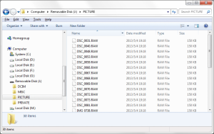
After conversion is accomplished, you will get a bunch of .RAW files in the output folder. Now plug in the SD card to your computer, create a PICTURE folder on it and copy the generated files to the folder.
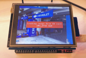
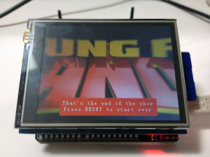
Now comes the Arduino part, all we need to do is uploading the sketch I wrote to Arduino, mounting the shield, inserting the SD card. Sit back and watch your pictures showing one by one on Arduino.
 Check out more details on